Op-Amp Applications: Mathematical Operations
Op-amps can perform continuous-time analog math. With resistors and capacitors in the feedback network, they can add, subtract, integrate, and differentiate voltage signals. These circuits are useful in audio, sensor interfaces, control systems, filters, and waveform generation.
Learning Objectives
By the end of this lesson, you should be able to write the main equations for summing, difference, integrator, and differentiator circuits; choose practical component values; and identify the stability and error limits that make the real circuits differ from ideal textbook versions.
Inverting Summing Amplifier
An inverting summing amplifier adds currents at the virtual-ground node and converts the sum back to voltage.
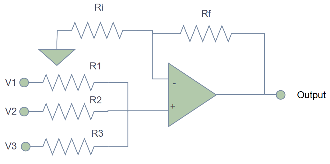
The general equation is:
[
V_{OUT}=-R_F\left(\frac{V_1}{R_1}+\frac{V_2}{R_2}+\frac{V_3}{R_3}+...\right)
]
If all input resistors equal (R) and (R_F=R):
[
V_{OUT}=-(V_1+V_2+V_3+...)
]
Different input resistor values create weighted sums.
Summing Worked Example
For an audio mixer:
- (V_1=1.0\text{ V}), (R_1=10\text{ k}\Omega)
- (V_2=0.5\text{ V}), (R_2=20\text{ k}\Omega)
- (V_3=0.2\text{ V}), (R_3=50\text{ k}\Omega)
- (R_F=10\text{ k}\Omega)
[
V_{OUT}=-10k\left(\frac{1.0}{10k}+\frac{0.5}{20k}+\frac{0.2}{50k}\right)
]
[
V_{OUT}=-(1.0+0.25+0.04)=-1.29\text{ V}
]
The output is inverted. Add a second inverting stage if a positive polarity is required.
Difference Amplifier
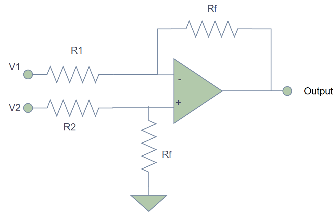
A difference amplifier subtracts two voltages. With matched resistor ratios:
[
V_{OUT}=\frac{R_2}{R_1}(V_2-V_1)
]
For unity gain with (R_2=R_1):
[
V_{OUT}=V_2-V_1
]
Resistor-ratio matching is critical. Poor matching converts common-mode voltage into output error and reduces CMRR.
Difference Worked Example
Two sensors read:
- (V_1=2.45\text{ V})
- (V_2=2.52\text{ V})
- gain (=20)
[
V_{OUT}=20(2.52-2.45)=20(0.07)=1.4\text{ V}
]
If both sensors sit on a large common-mode voltage, use an instrumentation amplifier instead of a simple four-resistor difference amplifier.
Integrator
An op-amp integrator uses a resistor at the input and a capacitor in feedback.
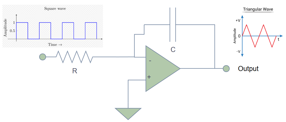
The ideal equation is:
[
V_{OUT}(t)=-\frac{1}{RC}\int V_{IN}(t),dt + V_{OUT}(0)
]
For a constant input:
[
\frac{dV_{OUT}}{dt}=-\frac{V_{IN}}{RC}
]
Integrators convert square waves to triangle waves, implement control-system integral action, and measure charge from current-output sensors.
Integrator Practical Limit
A pure integrator has infinite DC gain. Input offset voltage and bias current eventually drive the output into saturation. Practical integrators usually add a large resistor in parallel with the feedback capacitor to provide a DC feedback path.
The low-frequency break is approximately:
[
f_L=\frac{1}{2\pi R_P C}
]
where (R_P) is the parallel feedback resistor.
Differentiator
An op-amp differentiator uses a capacitor at the input and a resistor in feedback.
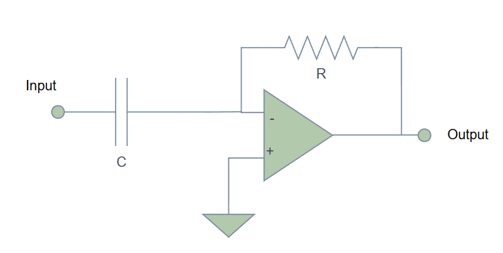
The ideal equation is:
[
V_{OUT}(t)=-RC\frac{dV_{IN}}{dt}
]
It responds to slope. A fast input edge creates a large output pulse.
Differentiator Practical Limit
Pure differentiators amplify high-frequency noise and can oscillate. A practical differentiator adds an input series resistor and often a small capacitor across the feedback resistor, limiting the useful frequency band.
Use the circuit as an edge detector or high-pass shaping stage only when the bandwidth and noise behavior are deliberate.
Application Comparison
| Circuit | Main function | Key formula | Practical risk |
|---|---|---|---|
| Summing amplifier | weighted addition | (V_{OUT}=-R_F\sum(V_i/R_i)) | clipping and source loading |
| Difference amplifier | subtraction | (V_{OUT}=A(V_2-V_1)) | resistor-ratio error |
| Integrator | accumulation | (V_{OUT}=-(1/RC)\int V_{IN}dt) | drift and saturation |
| Differentiator | rate detection | (V_{OUT}=-RC(dV_{IN}/dt)) | noise and instability |
Practical Checks
- Confirm output polarity and add inversion if required.
- Keep resistor values in a range that balances loading, bias current error, and noise.
- Use matched resistor networks for accurate difference amplifiers.
- Add DC feedback to integrators.
- Band-limit differentiators.
- Check output swing, slew rate, and gain-bandwidth for the expected waveform.
Common Mistakes
- Treating a simple difference amplifier like a precision instrumentation amplifier.
- Letting an integrator saturate because no DC feedback path exists.
- Building an ideal differentiator and amplifying noise.
- Forgetting that summing amplifiers invert polarity.
- Using high resistor values without checking input bias current.
Summary
Op-amps can implement analog math by turning voltage inputs into currents and controlling the feedback relationship. Summing amplifiers add weighted signals, difference amplifiers subtract, integrators accumulate over time, and differentiators respond to slope. The ideal equations are powerful, but real circuits need matching, bandwidth limits, DC paths, noise control, and output headroom.
Further Reading
- Analog Devices, "Op Amp Applications Handbook," mathematical operation circuits.
- Texas Instruments, "Op Amps for Everyone," active filters and integrators.
- Horowitz and Hill, "The Art of Electronics," op-amp applications.